Table of contents
Updated - January 19, 2026
Starlink, In the context of EMF (Electromagnetic field) and health effects such as EHS (Electro-hyper-sensitivity), interest in the frequencies used and permitted transmission power is increasing as STARLINK access becomes more widespread.
This article lists the frequencies and transmission power of standard household technology to enable a comparison with the technology used by STARLINK.
STARLINK
Starlink satellites are stationed at an altitude of 1,150 km with an inclination of 53° and communicate with each other in the Ka band (27.5 .. 29.1 GHz UL, 17.3 .. 18.6 DL).
The terrestrial antennas transmit on 14.0 ... 14.5 GHz with a maximum permissible transmission power of only 2.5 W, and receive on 10.95 ... 12.7 GHz.
The antenna structure is completely shielded downwards. Radiation is only emitted upwards (towards the satellite).
The antenna itself consists of several hundred individual antennas, which together form a circularly polarized beam that can be swivelled electronically. This antenna technology is called phased array. Its advantage is a very high directivity.
The motorized antenna adjustment is only used to roughly align the antenna to the next satellite. Fine tuning is achieved via the electronic beam alignment of this antenna array.
The STARLINK app shows a schematic representation of the "beam" during the search and after the satellite has been found. Without knowledge of antenna technology and beam formation, you would hardly expect the representation to largely correspond to reality.
An integrated GPS transmits the terrestrial position for forwarding to the satellites. In this way, geographically closest satellites can be addressed and regional regulations can be taken into account.
Comparison of Starlink antenna V2 (Gen 2) and V4 (Gen 3)
Technically, the two versions differ visually in the antenna surface.
The V2 version was motorized and was automatically aligned horizontally and vertically to the best accessible satellite during setup.
Version V4 dispenses with the motor drive and leaves the alignment of the antenna to the user via the app. At the same time, it offers a faster and more stable connection and higher data throughput thanks to the larger antenna surface.
The power requirement is nominally around 30 % higher, but actually less than 30 W on average (without heating operation), i.e. just over half an ampere with a 57 V DC voltage supply.
A practical comparison is here documented.
Radiation diagram
Antennas are usually known as radiation diagrams, e.g. for radio antennas, directional antennas, WLAN antennas, etc..
In contrast to omnidirectional antennas, directional antennas have a "lobe" aligned in the corresponding direction, as is also known from microphones (omnidirectional, cardioid, supercardioid).
This is not possible with a Starlink antenna due to the constantly changing "beam" shape, as each measurement would only represent a snapshot of the current conditions.
In this respect, the frequent complaints from organizations in this regard are justified in theory, but cannot be implemented in practice.
opening angle
With Starlink antennas, the aperture angle is the horizontal and vertical field of view of the sky, such as the human field of view of the eyes without moving them.
The old, rectangular and motorized Gen2 antenna and the manually adjustable Gen3 standard or mini antenna have an all-round field of view of 110°, while the new Flat High Performance Gen3 antenna has an extended field of view of 140°.
HF radiation exposure
According to ICNIRP (International Commission on Non-Ionizing Radiation Protection), the limit value for RF radiation in the frequency range of 2 - 300 GHz is a field strength of 61V/m2, or 10W/m2.
According to FCC documents, the minimum safe distance for RF radiation is only 34 cm!
At a mounting height of 3m above ground, there is no significant radiation at a height of 1.5m. It is around 0.1 % of the limit value, i.e. less than 10 mW/m2.
As the antennas with Beam Forming through Phased array The „beam“ is always strongly bundled and directed towards the satellite (area) and has no lateral radiation cones, as is known from „old“ directional television antennas, WLAN antennas or microphones with regard to their directional characteristics.
Nevertheless, there is a small amount of leakage radiation in the immediate vicinity to the side and below the antenna. Hence the specification regarding the minimum distance of 34 cm with regard to compliance with the specified RF limit values.
Satellite coverage
Under this link you can see the current Starlink satellite positions. It is noticeable that a broad belt with a large number of satellites covers the earth, although there are hardly any satellites from Denmark, northern Great Britain and the whole of Scandinavia, etc. onwards, while the southern hemisphere, with the exception of Antarctica, has an almost identical satellite density.
A lower satellite density has more frequent connection interruptions and failures. While several satellites are connected in parallel in densely populated areas, in the northern regions there is often only contact with 1 ... 4 satellites. In poor visibility (weather) conditions, the connection to the current satellite may be lost shortly before the "line of sight" range of the following satellite, which can lead to downtimes of 3 ... 45 seconds (practical value).

WIRELESS INTERNET ACCESS
The domestic WLAN transmits with a longer range but lower data rate in the 2.4 GHz band (2.400 GHz - 2.4835 GHz) with a maximum transmission power of 100 mW, or in the 5 GHz band (5.150 GHz - 5.350 GHz, or 5.470 GHz - 5.725 GHz) with a shorter range but higher data rate, with a maximum permissible transmission power of 1 W.
WLAN antennas are omnidirectional antennas, i.e. they transmit in a circular pattern with almost identical power in every direction.
Walls, concrete ceilings, especially reinforced concrete, but also trees, rain and snow attenuate the frequencies all the more the higher the frequencies are.
This is why it used to be possible to receive television stations in the VHF band (below 300 MHz) more clearly during snowfall than those in the UHF band (above 300 MHz).
mobile
Cell phones use frequencies of 900 MHz with a transmission power of 2 W, or up to 1 W in the networks with 1,800 and 2,100 MHz.
Their antennas have omnidirectional characteristics and, like WLAN antennas, transmit and receive equally from all directions with the same power density.
Base stations transmit with 10 ... 50 W. Some stations, especially in conurbations, are only a few hundred meters away, in overland regions even up to 30 km. They are generally designed as directional radio links with a relatively wide beam in the shape of a club, which achieve network-like, overlapping coverage of the respective area.
If a cell phone moves to the edge of a radio cell, the overlapping cell takes over.
Conclusion
The radiation intensity of base stations of cell phone network operators in urban centers, that of a WLAN in the immediate vicinity, such as at home, in offices, etc., but also that of a cell phone at the ear, is in each case incomparably higher than a STARLINK antenna above the human body can ever be.
Finally, currently determined radiation data:
measurement data 40 cm below the STARLINK antenna (EF Electric fieldRF High frequency power):
- EMF 0.01 µT
- EF 1.0 V / m
- RF 0.0001mW / m2
Cell phone measurement data (skin contact)
- EMF < 34.1 µT
- EF < 58 V / m
- RF < 270 mW / m2
WLAN measurement data (1 m distance)
- EMF 0.02 µT
- EF 1.0 V / m
- RF 5.652 mW / m2
Topics suggested by readers
„... We have the problem that our neighbor has set up a Starlink antenna on the roof of his bungalow about 8m away, which is aimed directly at our balcony. ...„
As outlined at the beginning, the Starlink antenna is NOT a conventional antenna with an omnidirectional characteristic, i.e. it transmits in all directions.
The antenna receives hemispherically (field of view 110°), as can also be seen in the diagram of the Starlink app.
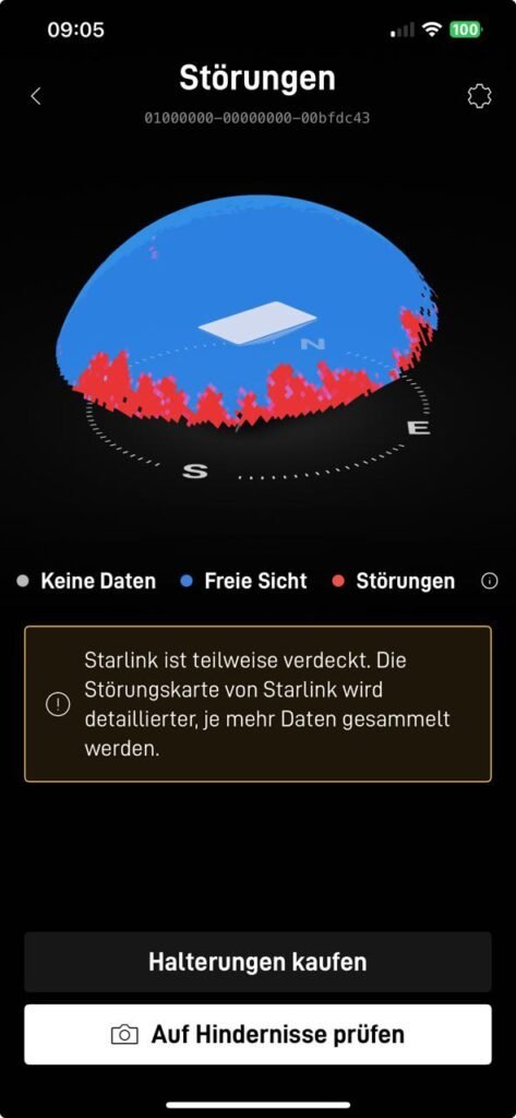
The area marked in blue shows the unobstructed view of the sky, i.e. the unobstructed view of the Starlink satellites, while the red areas represent the "obscured" view.
The antenna is constantly searching for satellites. As these are not positioned geostationary, but follow their orbits, the antenna must follow this satellite on contact, while keeping an eye on the rest of the sky in order to see the next satellite appearing on the horizon and to establish and maintain a connection on stand-by in parallel. If the currently connected satellite disappears from the field of view, the connection is transferred to the other satellite that has just entered the field of view.
The process is imperceptible, as the satellites also communicate with each other. Now it becomes clear why omnidirectional radiation would be complete nonsense for the specific application. A targeted, bundled "beam", as shown schematically in the app, is therefore the only practical way to make data transmission as effective as possible.

This "beam" does not necessarily have to be aligned at an angle of around 90°, as shown here in the diagram. If the antenna (version Gen. 2) is also motorized, this alignment only serves to detect the middle of the section of the sky supplied with satellites. The actual "beam" alignment is purely electronic, in that individual antenna elements of the antenna array are dynamically interconnected. This enables the "beam" to be tracked to the passing satellite without physically moving the antenna.
Therefore, radiation exposure does NOT exist where there are obstacles, such as a house, a balcony, etc., but only where there is a clear view of the sky.
The high transmission frequencies cannot penetrate any obstacles. The higher the frequency, the greater the attenuation caused by obstacles. Where there are obstacles (red area), no antenna element will attempt to transmit.
So if you climb onto the roof of the house and happen to step into the "beam", the antenna will immediately recognize the person as an obstacle ("covered"), switch off the active antenna elements and activate the neighbouring antenna elements that have a clear "view".
Here, the intelligence of the control unit is very sophisticated in its own interest, because the maximum permissible 2.5 W transmission power should not be wasted, but used to establish and maintain the Internet connection in a very targeted manner.
Of course, this is very beneficial for radiation protection and, in contrast to the general and ubiquitous 5G radiation, makes Starlink technology very appealing from a health perspective.
Hello Achim,
Thank you for providing the radiation data! We have the problem that our neighbor has set up a Starlink antenna on the roof of his bungalow about 8 m away, which is aimed directly at our balcony. Could you perhaps measure the radiation data of the Starlink antenna at a distance of approx. 5 to 10 m with frontal irradiation?
Many thanks and best regards
Isabell
Isabell,
Did you read the article? It is a phased array antenna which won't give a consistent radiation pattern due to the beam steering. If it is pointing towards you it won't necessarily be transmitting towards you because the 110 degree directional beam angle. At 14Ghz frequency, buildings aren't very RF transparent so the transmission beam won't be pointing at your balony but the satellite in the sky. You might catch a sidelobe but at 2.5W max output but I don't think you will have a problem at that distance. I doubt if the antenna will transmit unless it can "see" the receiving satellite whic will need an unobstructed view.
Dave.
Dave,
Thank you for your answer to Isabell's question.
My article has added to her question.
You confirm my comments.
Best regards to your hometown!
Achim