Table of contents
Updated - October 28, 2024
Pumps installed in motorhomes often do not provide the necessary pressure to operate an osmosis system. For this reason, an alternative solution is presented here that can be operated with a conventional pressure pump in the motorhome.
alternative
The alternative consists of the same four filters that are usually arranged in front of the osmosis membrane: PP filter 10 µm (filters according to the manufacturer - sand, impurities), GAC filter carbon filter (chlorine, organic pollutants, pesticides, insecticides, solvents), CTO filter activated carbon 5 µm , UF filter 0.02 µm (bacteria, viruses).
The osmosis membrane and the two subsequent activated carbon and remineralization stages are omitted, as is all other technology such as the control unit, pump, etc.
Advantage: Minerals remain in the water, which is why neither taste nor conductivity are changed and the usual remineralization is unnecessary. This also results in a consumption-cost advantage.
UV-C replaces osmosis membrane
A 254 nm UV-C system replaces the osmosis membrane responsible for (relative) sterility. An optional throttle valve enables the exact setting of the desired flow rate, whereby a sterility level of over 99.99 % can be achieved.
In practice, with a hose diameter of 6 mm and the Shurflo 2095-204-412 pressure pump, a flow rate of 1.5 liters per minute has been achieved - without the use of a flow rate limiter - which is below the required 1.6 liters per minute in relation to the 99.99 % sterility level.
Function of the filter unit
As the UV-C unit with a UVT (UV transmission) of 90 % is located BEFORE the filter unit, no germ-contaminated water reaches the filter inserts. So why do we still need the filters?
Well, on the one hand, UV-C irradiation does not remove substances such as hormones, drug residues, pesticides, etc., but "only" destroys the genetic code, the DNA of bacteria and viruses. On the other hand, non-reactivatable bacterial / viral fragments remain after UV-C irradiation, which are removed by the last 0.02 µm filter (or optionally available filter of only 0.01 µm - ultra-filtration).
However, drug residues, hormones and pesticides are filtered out by the 0.02 µm filter membrane, for example (see also the study Removal of steroid micropollutants by polymer-based spherical activated carbon (PBSAC) assisted membrane filtration). That's why this filter stage is essential!
Switching via 2-way valve
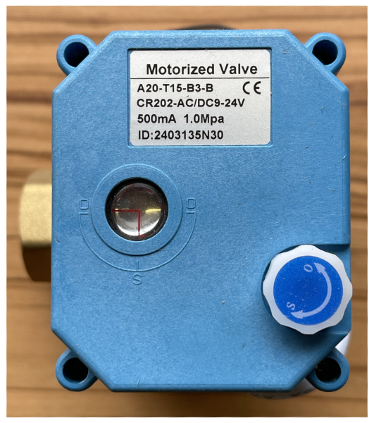
A motorized two-way valve switches between the water sources tank and UV-C filter system. In idle mode, the two-way valve connects the tank and tap. When switched to UV-C, the two-way valve switches to the UV-C filter system and tap.
Why is it important to pay attention to the polarity of the electrical valve connection? Power consumption in the motorhome should be kept as low as possible on the consumer side, as electrical energy is only available to a very limited extent.
For this reason, the normally permanent paths are routed to the branch that is energized without voltage, while the energized state causes the temporary connection position.
A second two-way valve in the outlet branch of the filter unit switches between the UV-C and filter unit to the tap in order to convey any stagnant water into the waste water tank before switching to the tap and discharging the germ-free water.
This can be done via a timer or SmartHome. The time period should be set so that the water content of the filter unit and the piping has been completely filled with fresh water by the time it reaches the tap outlet.
In the de-energized state, the connection water tap filter unit should be active; when energized, it should be switched to waste water. The valve shows the current position of the slider via a viewing window on the top and indicates the - de-energized - connections.
Conversion measures
The necessary modifications are limited to the production of a new holder for the filter unit consisting of the four filters described, the relocation of the display unit of the UV-C system to a central point in the kitchen area of the motorhome via a five-wire (control) cable, and the installation of the two two-way valves and their piping.
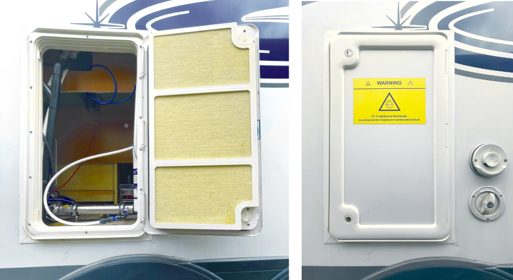
Where to put the system?
The where-to has already been described in a contribution to the Installation of osmosis and UV-C units have been described.
The solution in the supposedly full "no-space" motorhome was simple. Not all free spaces are obvious. Sometimes you have to look behind the scenes, e.g. backlighting covers, removing waste garbage cans, to find hidden but free space here or there that can be accessed from the outside via a retrofitted service hatch.
Mounting the filter unit
The filter unit bracket can be made from an aluminum L-profile measuring 60 x 20 x 3 mm and a minimum length of mm. The holes for the filter mounting are transferred from the original bracket.
The narrow side of the L-profile is drilled with five holes (each slightly offset from each other in height) to fix the unit to a side wall, each with rubber buffers of approx. 4 mm thickness, decoupled from vibrations, using Torx screws 5 x 25.
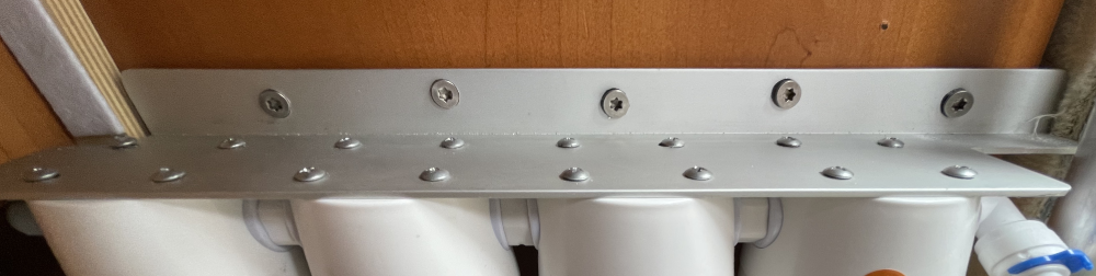
Self-adhesive foam rubber, which is stuck to the wall at a height of about 10 cm (measured from the floor), helps to dampen the vibration of the filter housing.
About 5 cm of space should be left underneath the filters so that they can be replaced if necessary.
Please note: the left-hand (inlet 6 mm) and right-hand (outlet 10 mm) connections are attached in opposite directions and cannot be rotated, which is why you must ensure that there is sufficient space for the left-hand hose so that it can be laid without kinking or, if necessary, inserted at a 90° angle.

Mounting UV-C filter
Mounting the 254 nm emitting UV-C irradiation unit with a UVT (UV transmission) of 90 % is mounted on two hanger bolts anchored in the floor with attached, rubber-covered, and thus vibration-damping, tube brackets.

Power supply outgoing on the left (black cable)
The UV-C unit should be aligned with the cable pointing towards the control unit and the cable should be laid in a wide radius.
The choice of holes for the hanger bolts must allow the connection of a 90° angle on both sides without them colliding, e.g. when closing the service flap.
Filter and UV-C unit connection
Only the filter unit has a defined 10 mm inlet and 6 mm outlet. The UV-C unit can be adapted to the piping as required via the 1/2″ connection.
A motorhome pipe is usually designed with 15 mm. Here, it was reduced to 12 mm, especially as it ultimately has to be further reduced to 10 mm or 6 mm.
The hose sections should not be too short when connecting the individual reducers. At least two centimetres allow for flexibility, albeit slight, and easy insertion of the retaining rings. These serve to protect against unintentional loosening of the connection.
When connecting the hoses to the connectors, make sure that the hose is pushed into the connector up to the end (about one centimeter) after overcoming the first resistance (the retaining tabs).
Sometimes you are mistaken and are delighted with a fountain ...
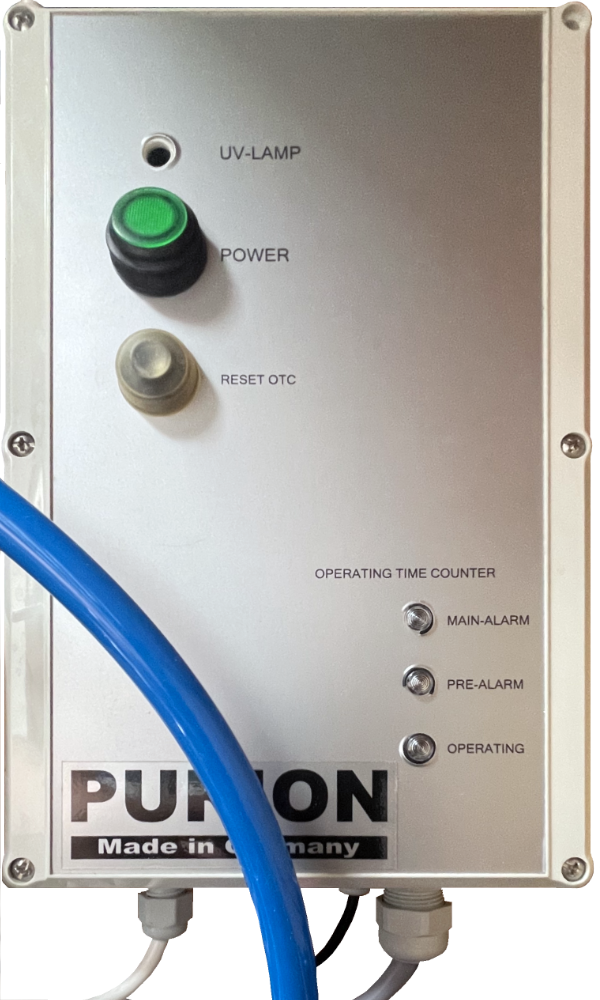
Electrical modification of the UV-C control unit
The unit displays the function and status of the UV-C lamp via LEDs. These must be installed externally so that they are visible in the kitchen area.
The housing cover can be carefully removed after loosening six Phillips screws: The electronics and LEDs are attached to the rear with two screws.
The electronics, which are attached with two Phillips screws, house the processor that monitors the service life of the UV-C lamp, as well as the NVRAM (non-volatile memory), which adds up the operating times and switches off accordingly at the set service life, but also controls the three status LEDs.
The entire circuit is only supplied with operating voltage via two cables. One of these still leads to the power switch.
The operating light is connected to the ballast unit, which is attached to the base of the housing, via two additional cables.
The two cables for the control electronics, the two cables for the operating LED and the second (red) cable for the on/off switch must be laid in the kitchen area using a five-core control cable.
Cable ducts are implemented vertically downwards with sealing cable glands.
Black cable Power supply UV-C lamp
Right cable gland Control cable
The now empty opening of the operating LED should be closed with a suitable cover cap.
The control electronics of the UV-C unit fits into the electronics box of the osmosis system, from which the adhesive foil on the front is removed and replaced with a self-made one if necessary.
Three existing holes in the housing, drilled out to 5 mm, accommodate the three suitably bent LEDs. The operating light fits into one of the existing holes (top right here).

The three status LEDs in the bottom row of holes on the right
The cables are routed through the housing cut-out for the former connector strip.
Pipework
To illustrate the piping more clearly:
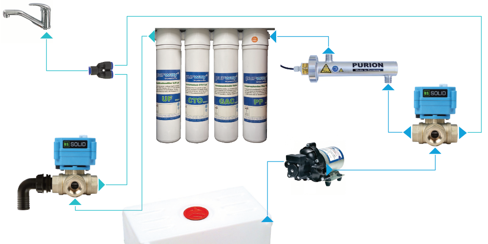
For the sake of simplicity, reductions are not shown in the diagram. The actual installation usually requires elbows and transition fittings from ½" to the metric hose dimension, as all fittings are designed in ½".
circuit diagram
The electrical connections are explained in the graphic circuit diagram, which is easy to understand even for technical laymen:
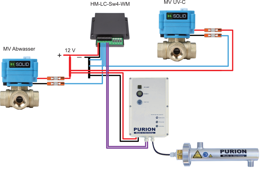
The motor valves can be connected regardless of the polarity. As soon as voltage is applied, regardless of polarity, the switching process starts. If the voltage is switched off, the valve returns mechanically to the rest position.
The UV-C unit must be connected with the correct polarity in the housing (control box). The modification of the internal circuit is described above. The purple wires represent the connections (red wires) on the power switch.
Control system
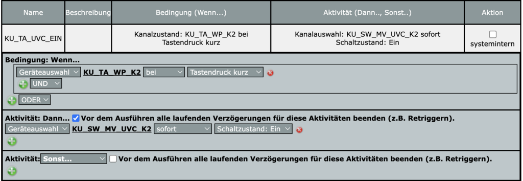
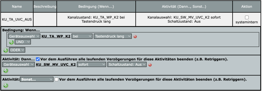
The solution chosen here was SmartHome (Raspberry Pi and Homematic). In conjunction with the dual push-button, which is already used for time-controlled switching on and off, the UV-C and the filter unit are activated via a channel with a short press of a button and deactivated with a long press of a button.
When switching on, the UV-C unit and both 2-way valves are switched on. The upper right valve in the illustration then connects the pump to the UV-C unit, while the left valve connects the outlet of the filter unit to the waste water pipe.
This connection is maintained for the duration of the flushing of the filter unit. The left-hand valve then switches the outlet of the filter unit to the branch to the tap. Germ-free water is then available for withdrawal.
When water extraction is complete, a long press of the button ensures that both valves are reset without voltage, establishing a direct connection between the pump and the tap, bypassing the UV-C and filter unit.
programs
Only four small programs are required:
- Switching on the UV-C unit using the button
- Switching off the UV-C unit using a button
- Switch on time control
- Time control switch off
Devices
A 2-gang push-button (e.g. HM-PB-2-WM55) and a 4-gang switching actuator (HM-LC-Sw4-WM) are required. The names of the channels have been chosen at random and can be adapted as required.
Channel designations
- KU_TA_WP_K2 - Push-button channel 2
- KU_SW_MV_UVC_K2 - Switch actuator channel 2 switches solenoid valve to UV-C unit
- KU_SW_UVC_LAMPE_K1 - Switch actuator channel 1 switches UV-C unit
- KU_SW_MV_ABW_K3 - Switch actuator channel 3 switches solenoid valve for waste water drainage
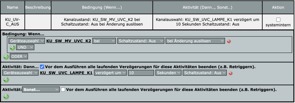
Switching on the UV-C unit using the button
Switching off the UV-C unit using a button
Switch on time control
Pressing the button switches the solenoid valve. This in turn triggers the following program, which initiates the switching on of the UV-C lamp and the operation of the waste water valve for (here) 90 seconds and switches to the water tap after this period has elapsed.
The time it takes to completely remove the stagnant water from the filters and the volume of the other pipes before fresh water can be drawn off depends on how full they are.

Time control switch off
The program is also started by switching the solenoid valve and switches the UV-C lamp off after the set time of 10 seconds (here) has elapsed.
This ensures that all germs in the UV-C unit have been reliably destroyed, thus ruling out the possibility of recontamination.
TDS measurement
In connection with osmosis systems, the TDS measurement (Totally Dissolved Solids) as proof of efficiency. The measuring devices therefore measure the components dissolved in the water and indicate these in ppm (parts per million) or in S (Siemens) to.
Approximately 2 μS/cm stands for 1 ppm (mg/L). The TDS factor for surface water is generally between 0.5 ... 0.8, averaged 0.65, corresponding to 280 μS/cm or 179 ppm.
The result depends on the concentration and mobility of the ions, as well as the temperature of the solution and, of course, the quality of the measuring device and its previous calibration.
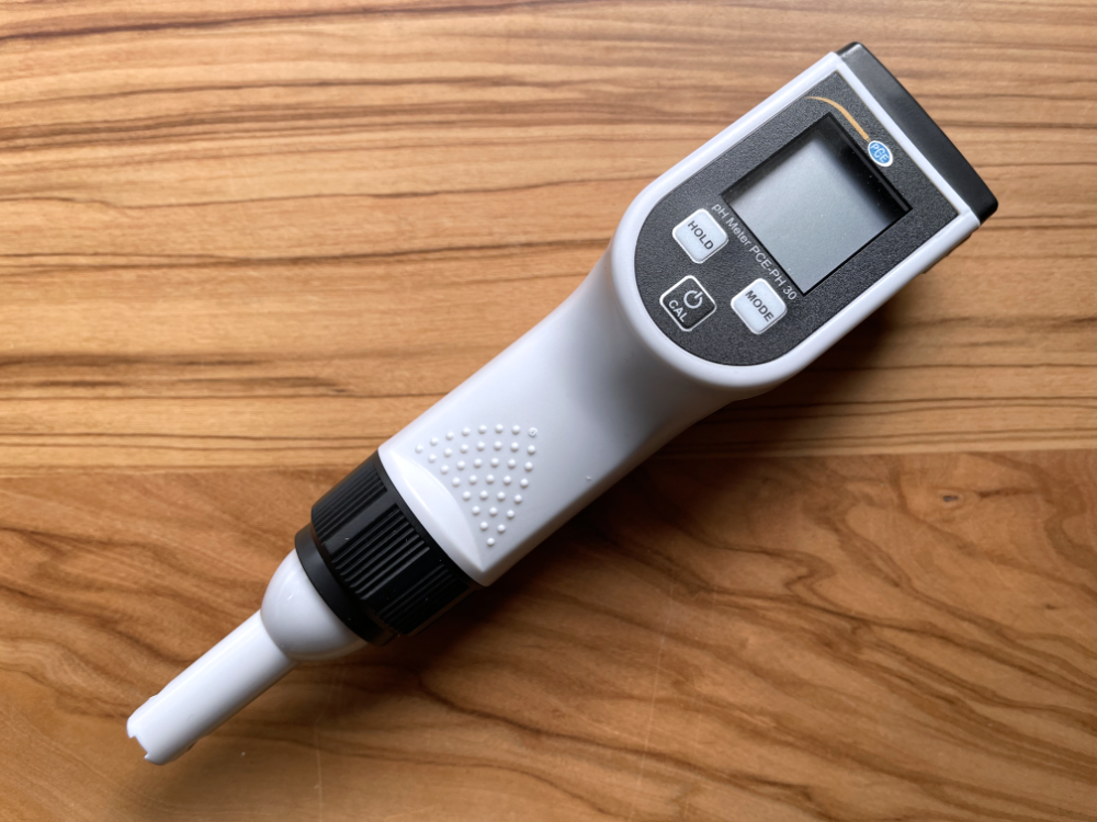
A useful device is, for example, the PCE-PH 30 in the calibrated version, including case and calibration solutions, as well as a calibration certificate.
While values around 40 μS/cm are considered normal for osmosis water, tap water has between 170 ... 370 μS/cm. The aim of water filtration - without an osmosis membrane - should therefore be a value around 200 ... 300 ppm, which is based on pure mineral content.
Mechanical filtration down to 0.01 or 0.02 μm also achieves a sterility level of around 90 %.
UV-C treatment leads to the destruction of all microorganisms such as bacteria and viruses. With sufficient irradiance (to prevent the enzymatic reconstruction of UV-damaged DNA by photolyases), sterility of up to 99.9999 % can be achieved.
Maintenance costs
The maintenance costs for replacing the filter once a year are very limited. The service life of the UV-C lamp is 10,000 operating hours, which means continuous operation for over a year, meaning that a replacement in around five years should be more than sufficient.
Conclusion
If you want to leave the taste of the water largely untouched, i.e. maintain the mineral content, but still want to enjoy water of any origin without germs, the alternative solution shown here is a good choice.