Table of contents
Updated - February 21, 2025
Refrigerator temperature control after converting an absorber to operation with a compressor unit is an unavoidable necessity, as the control system also became obsolete when the absorber technology was removed.
Anyone familiar with the blog here will assume that the control task will of course be carried out via SmartHome, which saves a considerable amount of mechanical work.
The reader is initially right about this, but for all those who would prefer to control it electronically (instead of using the mechanical thermostat supplied) without SmartHome, there is also an option designed for 12 V DC on-board voltage.
One reason to install the electronic control system in addition to the SmartHome version may be, for example, to be able to control the refrigerator independently of SmartHome even if it fails.
Both solutions are presented below.
... without SmartHome
The STC-1000 is a digital thermostat module with temperature sensor and 12 V DC supply. The module has two modes (Heating / cooling) and can therefore be used universally. Here, only the switching output Cooling used.
Addendum: This module has proven NOT to be suitable, no support. In this respect, this device is being returned.

Now that "cheap" has - once again - proved to be a misnomer, the renowned Italian manufacturer LAE the temperature controller, which can also be operated with DC 12 V and has identical installation dimensions LTR-5CSRD installed.
It costs, via the company engineer cy around 34 euros (plus freight costs of 30 euros), while the same device is otherwise available in Germany for up to just under 140 euros. Delivery took place within three working days. The control accuracy here is excellent with an average of approx. ± 0.5 °C.
Although the following description refers to the STC-1000, it also applies to the LTR-5CSRD due to its identical size and basically identical connection.
Electrical connection
The DC polarity can be connected as required, as the module ensures the correct supply via a rectifier.
The sensor cable can be extended if necessary. However, the extension should be as short as possible and with a thicker cross-section in order to keep the additional cable resistance low and not distort the measured value too much.
The compressor WEBASTO Compact Classic has a mechanical thermostat with two connections (C / T) takes over the switching on and off of the compressor.
These two connections are connected to the relay connection Cooling (the two terminals on the far right) of the LTR-5CSRD.
If the set temperature is exceeded, the relay switches the compressor on for cooling and switches it off again when the set temperature is reached.
Mechanical installation
Dometic absorption refrigerators usually have a panel between the freezer and refrigerator compartments in which the control panel is embedded.
As this is no longer required after the conversion, it is a suitable future installation location for the LTR-5CSRD module.

At the same time, the ribbon cable of the old control unit is ideal as a cable pull-through aid for the two required cables (power supply and control cable).
In addition, a hole for the temperature sensor can be drilled in the cable gland behind the cover to allow it to enter the interior. This means there is no need to extend the sensor cable and the sensor can be brought to the scene of the incident as quickly and easily as possible.
The production of the cut-out in the bezel, like the housing part behind it, is somewhat complex, as the LTR-5CSRD module is unfortunately slightly deeper than the bezel.
If you have a Dremel (or similar), you can make the cut-out with a milling cutter and subsequent filing, or with an iron saw blade, starting from the existing rotary knob cut-out and subsequent filing.
Removing the cover
The trick to removing the doors of Dometic fridge-freezers, which can be opened on both sides, is that after opening one side, the two locking pins protruding from the right and left of the door frame must be pressed in at the same time (this can be done, for example, with firm TESA tape stuck tightly over the pins so that they remain pressed in). The side of the door that is still closed can then be opened and the door removed in its entirety.
The cover is held in place by the two metal pins on the right and left. The pins can be pulled out upwards to release the panel. Note that the refrigerator door is now also free at the top and is secured against slipping out by means of cardboard folded to fit between the door frame and the holding frame on the right and left of the refrigerator housing!
It is only necessary to remove one of the two doors, ideally the freezer compartment door. Standing in front of the refrigerator, you can hold the refrigerator door in the tilt position with your knee while you pull off the panel that has become free.
The control panel electronics of the absorber refrigerator are located in the cover. There are two white two-pin connectors and a 10-pin gray ribbon cable with a black plug. All connectors can be removed from the electronics and levered out of the holder. The wide, orange-colored display ribbon cable can be cut or (forcibly) torn off.

It should be noted that the magnet connected to a two-core black cable is still required for automatic switching of the interior lighting. It is located in a holder in the panel, aligned vertically to the lower refrigerator door, with the cable pointing upwards.


All other components can go into the round tray.
The two two-core connection cables for the power supply and relay are glued to the ribbon cable with insulating tape. Wrap the ends required for connection around a pencil and secure them with insulating tape so that there is sufficient cable available inside for connection to the STC-1000 module and it is not unintentionally pulled out completely from the outside.
Then open the lower ventilation flap on the outside and feel the hanging ribbon cable on the top right of the compressor and pull the two cables until they are hanging in a comfortable connection position or until they reach the resistance of the pencil wedged inside.

Now mark the cut-out to be made for the LTR-5CSRD module and make it using a multi-function tool and file. The left-hand side is cut out about one centimeter wider to create sufficient clearance for the cables.
The hole to the right of the cut-out is used with a 12 mm step drill at an angle of 45 degrees in the direction of the cut-out to feed through (from the inside to the outside) the magnet and its black, two-core cable.
The temperature sensor is inserted into the cooling chamber through a 4 mm hole drilled vertically upwards from inside the cooling chamber (approx. 4 cm from the front edge and approx. 2 cm from the left edge of the cut-out), protruding approx. 3 mm into the cooling chamber.
All three cable ends are stripped and fitted with wire end ferrules corresponding to the cable cross-section before they are correctly connected to the LTR-5CSRD module inserted in the panel cut-out and screw terminals are tightened to prevent loose contact caused by vibrations while driving.
Unfortunately, the module can only be locked against the front on one side with an orange module holder.
Finally, insert the magnet into its holder. Make sure that the magnet is positioned as far as it will go in its holder to ensure correct functioning.
The panel can then be moved into position, the two locking pins inserted and the door of the freezer compartment re-hung. Again, use adhesive tape to keep the locking pins pressed in so that the hinges can be released and engage with the locking pins.

Setup of the LAE LTR-5CSRD
Select and set parameters
- To access the configuration menu, press the up/down + X for 5 seconds.
- With the buttons on or away to select the parameter to be changed.
- With the button up/down display the value.
- The button up/down hold down and press the on or away to set the desired value.
When the button is released up/down the new value is saved and the next parameter is displayed. - To exit the menu, press the X or wait 30 seconds.
parameter
- 1SP – Set Point
- Desired temperature - SPL – Set Point Low (-50 °C .. SPH)
- Lowest temperature limit - SPH – Set Point High (SPL .. +150 °C)
- Maximum temperature limit - 1Y – Yield (HY / PID*)
– HY Hysteresis mode (1HY, 1CT)
– PID* Proportional-Integral-Derivative Mode (1PB, 1IT, 1DT, 1AR, 1CT) - 1HY – Hysteresis (-19.99 .. 19.99 °C)
- Permissible temperature difference between switch-on and switch-off
- positive value = cooling / negative value = heating - 1CT – Cycle Time (0 .. 255)
- Minimum time between two switch-on actions in seconds
(e.g. to protect the compressor during repeated short switch-on intervals) - 1PF – Probe Failure (ON / OFF)
Relay status in the event of an error (default = OFF) - OS1 – Offset (-12.5 .. 12.5 °C)
Correction value of the temperature display
*PID - In contrast to hysteresis control, PID mode dampens the control oscillations above or below the setpoint. The control is dynamic: the closer the temperature is to the setpoint, the shorter the subsequent switch-on time. The parameterization must be carried out very carefully, as the control limits via the parameters may lead to an oversensitive control. The parameters responsible for this are
- 1PB – Proportional band - (-19.9 .. 19.9 °C)
Control width - 1IT – Integral action time - (0 .. 999s)
Standard time - 1DT – Derivative action time - (0 .. 999s)
Differentiation time
Example
Target temperature 9,0 °C.
Temperature measured with IR thermometer in the center of the refrigerator 9 °C.
Temperature shown on the display 12.5 °C.
Difference value to the measured value -3,5 °C.
- 1SP = 9.0 °C (setpoint)
- SPL = 8,0 °C (Lowest temperature limit)
- SPH = 10,0 °C (maximum temperature limit)
- 1HY = 0.1 °C (hysteresis, temperature difference on / off)
- 1CT = 120 seconds (compressor on delay time)
- OS1 = - 3.5 °C (correction value)
... with SmartHome
In this variant, a temperature sensor, as it is more interesting in terms of price, a DifferenceTemperatureSensor of the type HM-WDS30-OT2-SM-2as well as a 4-channel control unit that can be operated with 12 V DC.Scoldactor HM-LC-Sw4-PCB needed.
Both devices are taught to the control center (CPU or RaspberryPi) and given descriptive names (e.g. DTS_K1 and SA_K1). The designation K1 refers to the channel to be queried or activated.
The K1 Switching contacts of the 4-channel switching actuator are connected to the connections C and T of the compressor. The relay is switched on programmatically depending on the measured temperature of the differential temperature sensor on channel 1 (K1) if the temperature is higher than the set temperature, or switched off if it is lower.
The temperature sensor can be fitted through a hole just above the vegetable compartment. In this way, the sensor can be fitted with a pull-through aid even when the refrigerator is installed.
The control program
The line contained in each of the following illustrations dom.GetObject can be omitted: it is only used to call a script to record the switch-on and switch-off time and calculate the operating time. The last line SV_KS_AUS_Set can be omitted and serves the above purpose.
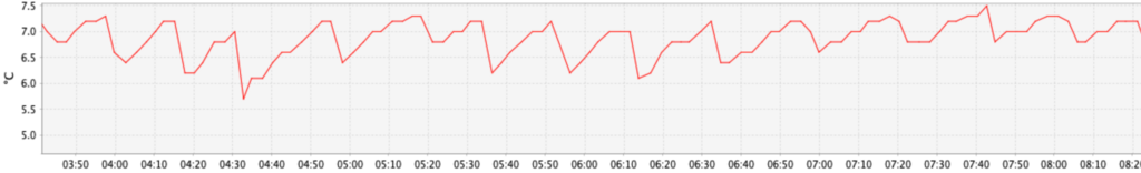
The switch-on / switch-off temperatures only differ nominally by 0.1 °C and are adapted by the hysteresis of the sensor and the time difference of the transmission intervals. Measured values are transmitted at 180 second intervals. This alone results in temperature differences of more than 0.1 °C.
Switch on the compressor

Switch off the compressor
