Table of contents
Updated – April 24, 2024
When installing PV modules on mobile homes, too little attention is often paid to certain things that later lead to a loss in yield or component failures.
Choice of PV modules
The choice of modules should be based on the principle of “highest yield with smallest dimensions”. Depending on the roof area, more than one module can be installed. These should then have identical technical data in order to be free to choose Parallel and/or series connection to be able to be.
Elevated installation
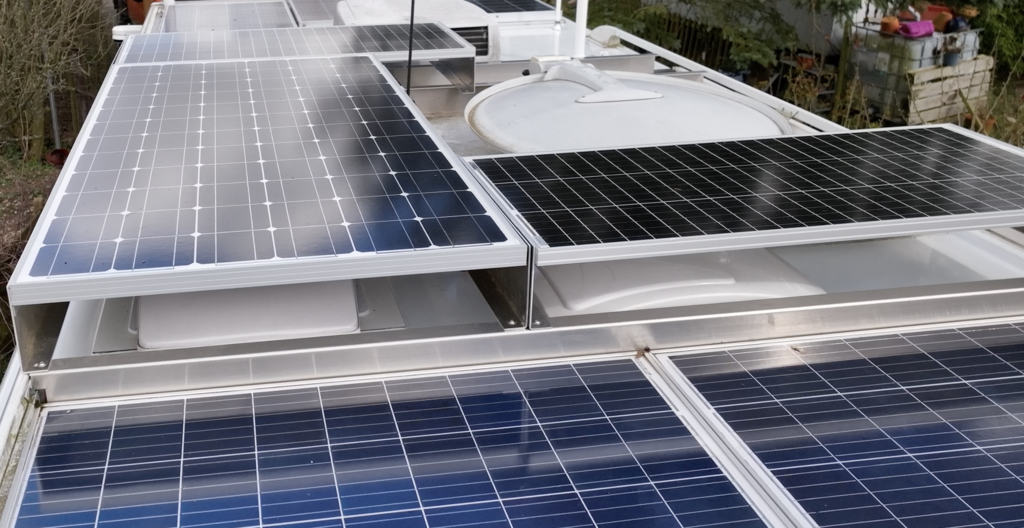
If the highest possible yield is required, the modules can also be installed across the entire surface of roof hatches. In addition to using the maximum area, this also provides effective hail protection for the roof hatches, which tend to shatter in the event of hail.

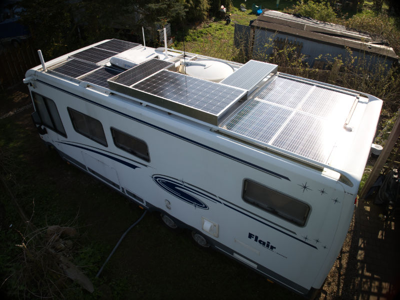
Modules installed via two Maxxfan roof hatches - 30 cm above the roof membrane to ensure the roof hoods can be opened completely. The roof distance is achieved by two aluminum U-profiles, each 150 mm apart, mounted at 90° offset.
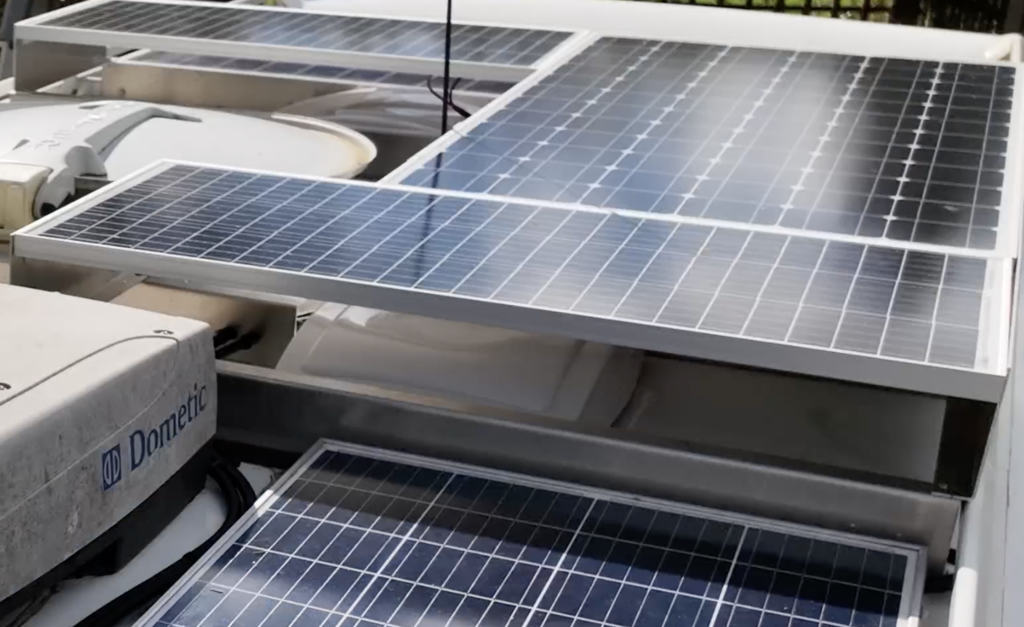
Here is the third Maxxfan roof hatch. The modules close with the cover of the Dometic air conditioning system.

Self-adhesive PV modules (films) are not recommended. PV modules require rear ventilation, which is necessary due to convection when installed on (house) roofs, in order to prevent overheating. These flex modules were primarily developed for yachts, sailboats, etc., i.e. maritime applications in which susceptibility and wind resistance are eliminated.
There are 10 modules of 100 W each and one of 200 W, a total of 1.2 kW, which feed into 4 x 280 Ah LiFePo4 batteries and supply a 3 kW Victron inverter.
With the elevated construction method (self-)constructed here for the three modules, one could easily have installed 1.6 kW PV (with less assembly effort) if this type of assembly had also been used for the other two module groups...

More mounting options
Motorhomes in the panel van version already have attachment points on the roof for roof racks, which can be used as attachment points for the holders of the PV module carriers.
Other motorhomes have attachment points to an existing (and removable) railing, which can be used to mount the brackets for the PV module carriers.
Mounting material
It is advisable to use conventional assembly materials, such as those used in PV systems on pitched roofs. They are comparatively cheap due to the number of units, they are also designed to withstand storms (100 km/h speed can also mean 130 to 150 km/h wind speed) and the modules can be assembled quickly because of the standardized components.
If you have to improvise, as described above, the assembly effort increases significantly and the maximum achievable yield is reduced. Anything “tricky” should be avoided.
Electrical material
Don't save money at the wrong end! Prefer higher diameter cables to cheaper, thinner ones. Order plus cable in red, minus cable in black. Do not simply cut cables and crimp/connect them with cable connectors.
Even specialist companies choose to forego proper plug connectors for some unknown reason, although the pre-wired modules are usually equipped with cable lengths and plugs/sockets that allow a direct connection without any problems. It may be that you want to save yourself the trouble of arranging the cables and fastening them with cable ties, but such sloppy workmanship will pay off in the event of corrosion, etc. at the latest.
I had 2x 4 PV modules of 100 W each installed by a specialist company. The yield after a few months was about 10% in full sunlight. When checking the assembly and connections, it turned out that a quartet of modules was only connected with a stranded wire. Moisture and leakage currents led to complete failure of the unit.
Cable roof feedthrough
“Normal” distribution boxes such as are also suitable for cable entry Spelsberg A-Box, into which you can, if necessary, sideways Cable glands can attach.
The roof ducts that are common for motorhomes are usually glued on and can therefore no longer be fitted with additional cables when expanding.
The position of the roof duct should be in the area of the rear garage or a nearby cupboard so that the cables can be laid cleanly, if necessary also in cable ducts. The shortest route is the best here.
Here I used a 40mm step drill to create a generous roof opening. The hole was lined with a 40 mm HT pipe to protect the cable, with a slight overhang above and below the roof membrane.
A similar hole was then made in the A-Box and placed congruently onto the protruding HT pipe. The underside of the A-Box has a thick adhesive seam all around, which ensures an absolutely watertight seal when pressed onto the roof surface.
If necessary, connectors for connecting cables can also be accommodated within the A-Box, provided it is large enough.
It is advisable to prepare a precise wiring plan beforehand, the quicker the functionality will be established after installation.
Connection of PV module(s) to MPPT controller
The connections of the PV module cables to the MPPT controller should be made with cable end sleeves in order to be able to create a clean, coherent and wire-friendly connection.
If several module groups are used (here, for example, 3x 4 module groups of 400 W each), several MPPT controllers may have to be used if the technical data differ.
Several MPPT controllers have the advantage that partial shading can be controlled more optimally, and if one controller fails, the entire system is not left idle, but only part of it fails. If you rely on a constant energy supply, you should invest in an additional MPPT controller if you have more than one module.
Connection MPPT controller output to battery(s)
The output of the MPPT controller is connected directly to the battery(s). Several MPPT controllers may not (!) simply be bridged on the output side, but rather each of them should be connected directly to the respective battery pole with a cable.
With three MPPT controllers, there are three plus and three minus cable connections from the controller outputs to the respective battery pole.
The connections to the battery poles must also be made professionally using cable ring shoes that correspond to the cable cross section in order to achieve the lowest contact resistance and thereby avoid losses and unacceptable heating.
The necessary cross-section of copper cables for DC applications can be calculated here, as can the voltage drop. The yellow fields are editable:
| cross-section | 17.2414 | sq. mm | voltage drop | 0.1979 | v |
| length | 10 | m | cross-section | 17.42 | sq. mm |
| Electricity | 10 | A | length | 10 | m |
| permissible voltage drop | 0.2 | v | Electricity | 10 | A |
| Conductivity CU | 58 | SI/m | Conductivity CU | 58 | SI/m |
All electrical connections must be tight and secured against accidental loosening (e.g. using self-locking nuts). Work on electrical systems must only be carried out by qualified specialist personnel!
ps If you need personal support in the implementation for a fee, you are welcome to Ticketing make!